Amplificador 2CH
Design do filtro FIR Max Power Class D amplificador para subwoofer
Item número.: D2-4500 DSP
Modelo: D2-4500 DSP
Canal: amplificador de potência de 2 canais
Característica: 1U/amplificador digital/2 Ohms estável
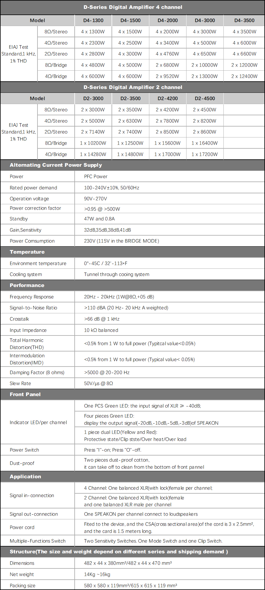
Potência de saída:
Potência estéreo de 8Ω (RMS): 4.500W X 2CH
Potência estéreo de 4Ω (RMS): 8.200W X 2CH
Potência estéreo de 2Ω (R
Canal: amplificador de potência de 2 canais
Característica: 1U/amplificador digital/2 Ohms estável
Potência de saída:
Potência estéreo de 8Ω (RMS): 4.500W X 2CH
Potência estéreo de 4Ω (RMS): 8.200W X 2CH
Potência estéreo de 2Ω (R
Descrição
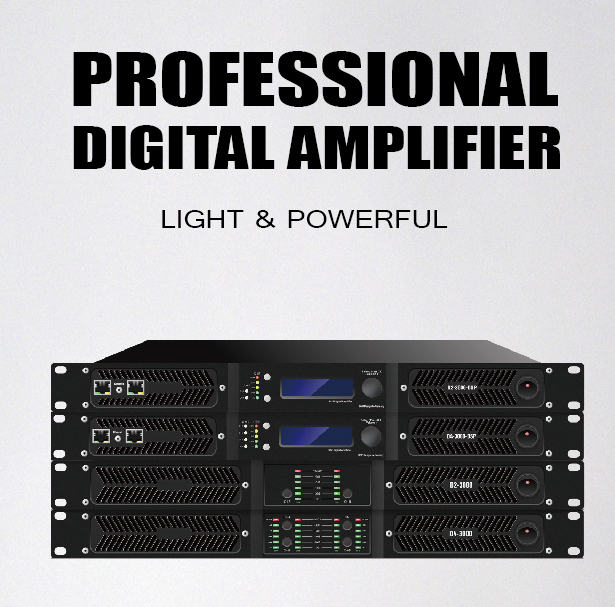
D2-4500 DSP FEATURE:
| ►2 x 8600W into 2ohms,2 x 8200W into 4ohms,2 x 4500W into 8ohms |
| ►Use Nippon Chemi-Con/Nichicon capacitors from Janpan |
| ►High Efficient Transistors,Lower heat generation,Low noise,low distortion |
| ►Stable at 2 ohms long-term load |
| ►Active PFC,soft-switching for high adaptability |
| ►Wide voltage range of 90V-270V for harsh environments |
| ►Efficiency,energy conservation, environmental protection |
| ►Standby sleep mode,power-saving and durable |
| ►Damp Factor >5000 @20-200Hz,groundshaking super bass |
| ►D2-4500 DSP is powerful for 18-inch/21-inch subwoofer! ►Fans can be replaced with Owl Mute Fans for Home Theatre(Requires additional price) |
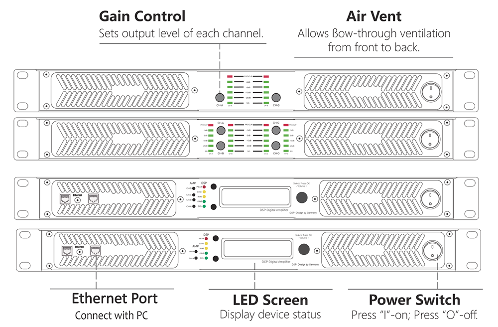
FRONT PANEL FEATURE
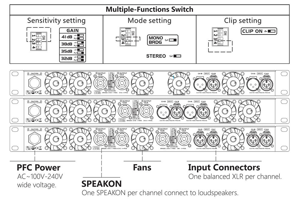
REAR PANEL FEATURE
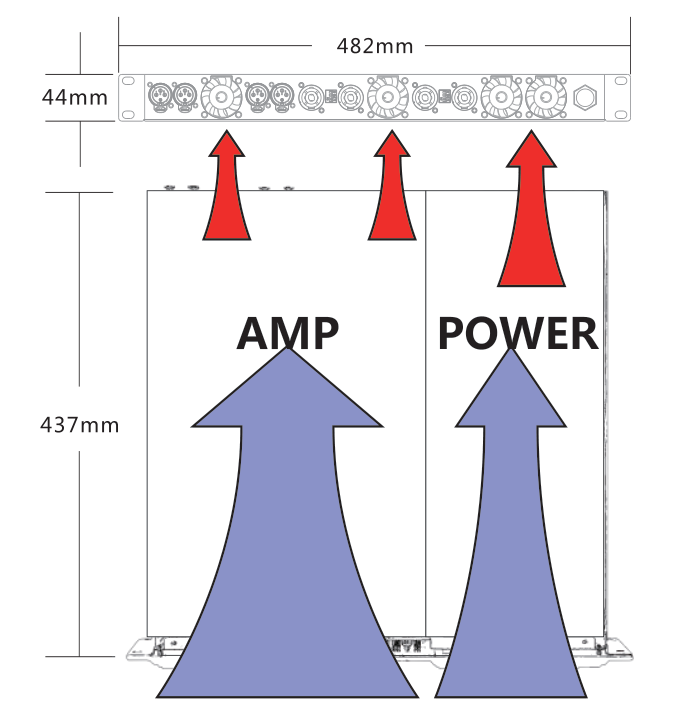
Dimensions and Cooling system
|
NOTE:
The size is 437mm inside of the device(without the cover plate and front panel).The size is around 472mm of the complete device,but a little bit different size in the different front panel.Some series with different size that had not shown,please learn it in the parameter. Tunnel through cooling system Cold air comes in from the front panel of the equipment, forms a duct through the radiator to take the heat away and out from the rear panel of the equipment. |
 |
ALLDSP ALLControl
The new D series digital amplifier also has the option to add a DSP function, Our D series DSP amplifier uses an ALLDSP system from Germany. It is suited for Windows, Mac and ios systems.
The application for iPad or iPhone can be downloaded and installed from the Apple Store.
App Name: ALLControl, Remind you it is Paid-for Software.(The software Password is Develo_p)
For the Remote Operation Software (Windows and Mac) and Manual, Please check the Download link or contact us!
Note that for a Windows computer, there are separate applications for Windows 32-bit and 64-bit.
|
Parameters of DSP Module
|
|
|
Digital signal processor
|
64 bit multimode, 4 in and 4 o]ut
|
|
AD converter
|
120db Dynamic Range
|
|
DA converter
|
110db Dynamic Range
|
|
Storage preset
|
100
|
|
Signal input
|
Analog/optional Dante
|
|
Delay range
|
0-10ms
|
|
Equalizer
|
5-segment grouping equalization, 10 segment input/output equalization
|
|
Frequency division filter
|
Linkwitz Reiley, Belsel, Butterworth
|
|
FIR filter
|
4x144taps
|
Attention: You cannot connect the unit to the network through the USB or Ethernet at the same time. You can only control the unit from one platform at the same time if you switch from one platform to another, you MUST shut down the control software at the previous platform first.
Local connectivity of the device to the control computer from a front-panel USB connector is also possible to download initial settings or as a fallback in case of network failure.
►Unit Window: Main Panel
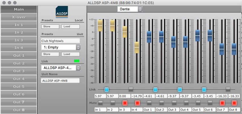
Unit window shows the unit window from which all setup screens and options can be reached.Clicking the exit cross will close the software but leave the network Control program running.
►Input Channel Settings Screen

Clicking on an Input channel number in the Unit window will bring up the input channel settings screen see Figure above. In this screen, individual input channels can be equalized and/or filtered.
Settings screen:
|
●Filtering and EQ
●Input channel transfer function curve ●Screen expansion and legends ●Input Gain, Mute ●Delay, limiter, compressor ●RMS compressor |
 |
●Screen expansion and legends On the left-hand side of the graphical screen are four icons to help precise settings. The top Arrow icon expands the graphical screen to the size of the window.Clicking this icon again from the expanded screen expands it to the full display size. In either of the expanded settings, clicking the X-icon at the top left will collapse the graphical area to the default setting. The T(ext) icon will place the frequency, Q and gain values of each EQ and filter setting in the graphical screen. For very accurate settings of EQ or filtering you can click the Looking Glass icon. |
 |
●Delay, limiter, compressor Settings for channel delay, limiter (-48 to +24 dBu) and Limiter release rate (10 to 100 dB/s) settings.Plus a button to enter the rms compressor menus.Channel delay can be set in a variety of distance or time units from the drop-down list. |
 |
●Compressor settings window Clicking on the compressor button brings up the compressor menu. In the compressor menu you can set the parameters of the rms compressor.You can set the threshold, attack, hold, and release time, the compression ratio and the make-up gain.Next to the controls is a VU meter that also displays the gain reduction (GR). Be sure to use the ‘Back’ button to return to the output menu. |
►Crossover Settings Window
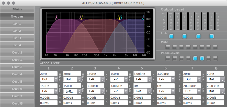
When you click X-over in the left unit window function list, most of the screen is dedicated to the controls and indicators for setting up the cross over filters as shown in Figure.
Settings screen:
|
●Graphical control
●Filter type ●Gain ●Delay ●Link ●Mute, Phase Invert |
►Output Channel Settings Screen

As shown in the picture above, faders are shown for each of the input channels. This will allow mixing each of the input signals to each individual Output channel. Even if Input channels are set to Linked in the Unit window, it is still possible here to mix individual Input channels to an Output channel in any desired ratio. Level setting are shown numerically below each fader. The available range is from -48 dB to 0 dB. As in other screen, double clicking a fader resets it to default.
A complete control screen is available for each Output channel. The graphical area reflects the Crossover settings for the channel in addition to any equalization settings set up in this screen, and is very similar to the available settings in the individual Input channel screens.The status of an element is always reflected in the blue on/off button next to each element.
Settings screen:
|
●Relationship between Input- and Output settings
●Output filtering and EQ ●Output channel transfer curve ●Delay, limiter, compressor ●RMS compressor ●Change / adjusting Values |
►More Dsp Details please download:
D Series AllDSP ALLControl Software Download (64 bit)
D Series AllDSP ALLControl Software Download (32 bit)
